
How to Choose the Right Hydraulic Pumps and Motors?

Choosing the right hydraulic pumps and motors begins with understanding the machine, not browsing a product catalog. Each component must match the required flow, pressure, speed, torque, and duty cycle. A compact excavator, injection molding machine, and agricultural sprayer need very different hydraulic solutions. The wrong choice may create overheating, unstable movement, excessive noise, or early component failure.

This guide explains how to connect operating requirements with practical component specifications. It examines displacement, volumetric efficiency, pressure ratings, shaft speed, control methods, fluid compatibility, and installation conditions. It also considers contamination, ambient temperature, maintenance access, and available replacement parts. These details often decide whether a system performs reliably after thousands of operating hours. A pump rated for 250 bar may still be unsuitable if it runs continuously near that limit.

Small details matter.

Real maintenance experience shows that manufacturers’ data sheets are essential, but they are not the entire answer. Actual performance depends on piping layout, filtration, alignment, oil condition, and operator habits. No selection method is perfect. Engineers sometimes prioritize maximum pressure and overlook low-speed efficiency or cooling capacity. That mistake can remain hidden until production slows or a motor begins to lose torque.

Reliable selection requires verified specifications, recognized testing standards, and advice from qualified hydraulic professionals. Compare the application’s real demands with the supplier’s documented limits. Leave a sensible safety margin, but avoid unnecessary oversizing, which increases cost and energy consumption. With a careful, evidence-based approach, hydraulic pumps and motors can deliver smoother motion, longer service life, and more predictable operating costs.
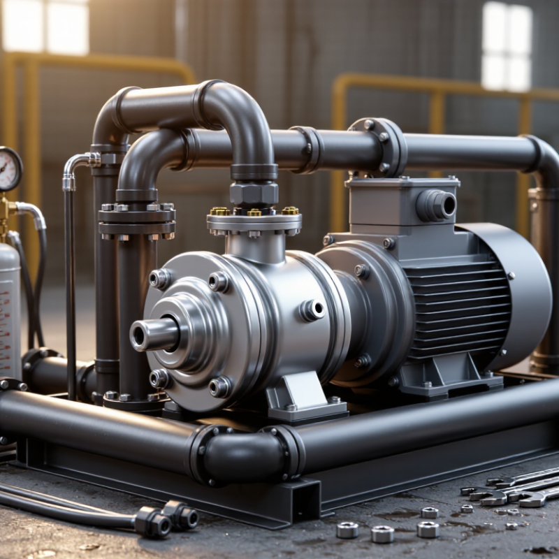
How to Choose the Right Hydraulic Pumps and Motors?

Define Duty Requirements: Flow, Pressure, Speed, and 90% Volumetric Efficiency

Choosing a hydraulic pump or motor begins with the real duty cycle, not the catalog’s maximum rating. Record required flow, pressure, shaft speed, operating hours, and load changes. The U.S. Department of Energy’s 2023 Motor Systems Market Assessment attributes about 69% of industrial electricity use to motor-driven systems. That figure makes efficient sizing financially important, even in compact hydraulic units.

Use the duty point to check displacement. For 40 L/min at 1,500 rpm and 90% volumetric efficiency, the required displacement is about 29.6 cm³ per revolution. Pressure determines torque and power. At 180 bar and 40 L/min, hydraulic power is approximately 12 kW before mechanical losses. ISO 4409 provides methods for testing displacement pumps and motors, including flow, torque, speed, and efficiency. Ask suppliers for test data under comparable oil temperature and pressure.

Ninety percent volumetric efficiency is useful, but it is not permanent. Leakage often increases with pressure, temperature, and wear. A cold test bench can look reassuring. Field conditions may disagree. I would recheck the calculation at minimum speed and maximum pressure, then compare the result with the expected duty cycle. Oversizing can reduce efficiency and response quality. Undersizing can create heat, noise, and premature wear. My first estimate may still be wrong if the machine spends most of its time unloading or idling. That operating detail deserves measurement.

How to Choose the Right Hydraulic Pumps and Motors?

Define the duty requirements first: flow determines actuator speed, pressure determines available force or torque, shaft speed affects displacement selection, and a design target near 90% volumetric efficiency helps account for internal leakage.

The chart compares representative hydraulic duty points. Flow is shown in L/min, pressure in bar, shaft speed in rpm, and volumetric efficiency as a percentage. Final pump and motor sizing should use the machine’s continuous and peak operating conditions.

Select Pump Type: Gear 80–90%, Vane 85–92%, Piston 90–95% Efficiency

How to Choose the Right Hydraulic Pumps and Motors?

Efficiency often guides hydraulic equipment selection, but the percentage on a data sheet needs careful reading. Gear pumps usually deliver 80–90% efficiency. They suit simple circuits, moderate pressure, and applications needing durable, economical service. Their compact design helps on mobile machines, although internal leakage can increase as wear develops.

Vane pumps commonly reach 85–92% efficiency. They operate quietly and provide smoother flow than many gear designs. This makes them useful for industrial systems where noise matters. Piston pumps can achieve 90–95% efficiency, especially under high pressure and carefully controlled operating conditions. They are more sensitive to contamination, incorrect installation, and poor fluid maintenance.

Real workshop results may differ. Temperature, viscosity, speed, pressure, and relief-valve settings all affect energy loss. I have seen a highly efficient piston unit waste power because a filter was restricted. That was not a pump failure. It was a maintenance mistake. Efficiency figures should therefore guide testing, not replace it. Check the required flow, peak pressure, duty cycle, starting load, and available cooling. A gear unit may be the better choice for a dusty, budget-sensitive machine. A vane design may reduce noise in a factory. A piston unit may repay its higher cost during continuous, high-pressure operation. Measure actual input power and hydraulic output when possible. Small errors matter.

How to Choose the Right Hydraulic Pumps and Motors? - Select Pump Type: Gear 80–90%, Vane 85–92%, Piston 90–95% Efficiency

Typical selection data for common hydraulic pump and motor technologies. Actual performance depends on pressure, speed, temperature, fluid viscosity, installation, and operating conditions.

Component Type Operating Principle Typical Volumetric Efficiency Typical Overall Efficiency Typical Pressure Range Flow Characteristics Noise Level Key Advantages Typical Applications Important Selection Considerations
External Gear Pump Two meshing gears transfer hydraulic fluid from the inlet side to the outlet side. Approximately 85–95% Approximately 80–90% Commonly 100–250 bar; some designs are rated higher. Fixed displacement with relatively stable flow. Flow pulsation is higher than in many vane and piston designs. Moderate to high, depending on speed, pressure, and housing design. Simple construction, compact size, low cost, good contamination tolerance, and straightforward maintenance. Material-handling equipment, agricultural machinery, hydraulic power units, lifts, and basic mobile equipment. Choose according to required pressure, flow, shaft speed, oil cleanliness, inlet conditions, and allowable noise.
Internal Gear Pump An internal gear and an external gear move fluid through expanding and contracting cavities. Approximately 90–97% Approximately 82–92% Commonly 150–300 bar, depending on design and operating speed. Low-pulsation flow with good suction performance and smooth delivery. Generally lower than standard external gear pumps. Quiet operation, smooth flow, and good performance with moderate-viscosity fluids. Industrial power units, lubrication systems, presses, and applications requiring low noise. Check minimum fluid viscosity, maximum speed, pressure rating, and compatibility with the hydraulic fluid.
Balanced Vane Pump Sliding vanes rotate inside a cam ring to create pumping chambers. Approximately 90–96% Approximately 85–92% Commonly 100–175 bar; specialized designs may support higher pressures. Smooth, low-pulsation flow; fixed or variable displacement versions are available. Usually low to moderate. Quiet operation, good flow smoothness, and efficient performance at moderate pressure. Machine tools, injection-molding equipment, industrial automation, and general hydraulic systems. Requires clean fluid and correct viscosity. Excessive contamination can accelerate vane and cam-ring wear.
Variable Displacement Axial Piston Pump Pistons reciprocate in a cylinder block; displacement is changed by adjusting the swash plate or bent axis. Approximately 95–99% Approximately 90–95% Commonly 250–450 bar; peak ratings depend on the specific design. Variable flow and pressure compensation are available. Flow can be matched closely to system demand. Moderate; noise may increase at high pressure or speed. High pressure capability, excellent power density, high efficiency, and reduced throttling losses. Excavators, presses, mobile machinery, hydrostatic drives, and high-performance industrial systems. Requires accurate sizing, clean fluid, suitable inlet conditions, and careful control of pressure, speed, and case-drain flow.
Fixed Displacement Axial Piston Pump Multiple pistons generate flow as they reciprocate in a rotating cylinder block. Approximately 94–98% Approximately 88–94% Commonly 250–400 bar, depending on construction and duty cycle. Fixed flow at a given rotational speed, with relatively low pulsation. Moderate. High pressure capability, compact design, and efficient operation under demanding loads. Hydrostatic transmissions, high-pressure power units, construction equipment, and test systems. Confirm maximum continuous pressure, intermittent pressure, rotational direction, case pressure, and minimum displacement conditions.
Radial Piston Pump Radially arranged pistons generate flow through eccentric or cam-driven motion. Approximately 95–99% Approximately 90–96% Often 300–700 bar, depending on configuration and service requirements. High-pressure flow with low leakage; pulsation depends on the number of pistons and porting design. Moderate to high, especially at high pressure and speed. Very high pressure capability, strong load capacity, and long service life when properly maintained. Hydraulic presses, clamping systems, test benches, injection systems, and specialized high-pressure equipment. Evaluate pressure ripple, speed limits, fluid cleanliness, cooling requirements, and total lifecycle cost.
Hydraulic Gear Motor Pressurized fluid drives meshing gears, producing rotary torque at the output shaft. Approximately 85–95% Approximately 80–90% Commonly 100–250 bar; verify continuous and peak ratings separately. Fixed displacement with torque proportional to pressure and speed proportional to flow. Moderate to high. Compact, economical, durable, and suitable for simple rotary drives. Conveyors, fans, augers, winches, agricultural machinery, and auxiliary drives. Check starting torque, allowable shaft load, case-drain requirements, speed range, and pressure at the motor inlet.
Hydraulic Vane Motor Pressurized fluid pushes sliding vanes against a cam ring to create rotary motion. Approximately 88–96% Approximately 82–92% Commonly 100–175 bar, depending on the motor design. Smooth rotation with low torque ripple and moderate speed capability. Low to moderate. Smooth operation, low noise, and good performance for moderate-pressure applications. Machine tools, fans, conveyors, packaging equipment, and continuous-duty rotary systems. Use clean fluid and maintain correct viscosity. Confirm starting torque and minimum operating speed for the load.
Hydraulic Axial Piston Motor Pressurized fluid drives pistons in an angled or swash-plate cylinder assembly to produce shaft rotation. Approximately 95–99% Approximately 90–95% Commonly 250–450 bar; specialized units may have higher ratings. Fixed or variable displacement, high torque density, and wide controllable speed range. Moderate. High efficiency, high pressure capability, strong starting torque, and precise speed control. Hydrostatic drives, winches, excavators, mobile machinery, and high-load rotary applications. Match displacement to required torque and speed. Check case pressure, cooling, fluid cleanliness, and control response.

Size the Motor: T = ΔpVd/62.8 and Allow 85–95% Mechanical Efficiency

Selecting a hydraulic motor starts with torque, not catalog size. Use T = ΔpVd/62.8 , where T is torque in lb-in, Δp is pressure in psi, and Vd is displacement in cubic inches per revolution. Then allow 85–95% mechanical efficiency. The practical equation becomes Tactual = ΔpVdηm/62.8 . For example, 2,500 psi, 5 in³/rev, and 90% efficiency produce about 179 lb-in. That number may look adequate, but startup loads can be much higher.

Field experience shows that pressure spikes, cold oil, and misalignment reduce real output. The U.S. Department of Energy reports that pumping systems can consume 25–50% of industrial motor energy. Hydraulic losses add to this burden. NFPA hydraulic design guidance also emphasizes rated pressure, displacement, and contamination control. A motor running near its limit may survive testing, then struggle beside a dusty machine. I would not treat 90% efficiency as guaranteed. It is an estimate requiring verification.

Tips: Measure pressure at the motor inlet, not only at the pump. Check the manufacturer’s displacement tolerance and shaft-speed limit. Add a sensible service margin, but avoid excessive oversizing. A larger motor can run inefficiently at light loads. Record oil temperature during operation. That small detail often exposes the real problem.

Cite: U.S. Department of Energy, Improving Pumping System Performance: A Sourcebook for Industry; NFPA hydraulic fluid power design guidance.

Specify Oil: ISO VG 32/46/68 and Cleanliness Target ISO 4406 18/16/13

Choosing a hydraulic pump or motor starts with the oil specification, not the catalog photograph. ISO 3448 defines ISO VG 32, 46, and 68 by viscosity at 40°C. Their permitted ranges are 28.8–35.2, 41.4–50.6, and 61.2–74.8 mm²/s. Higher viscosity can protect heavily loaded components, but it may increase startup resistance and heat. Lower viscosity improves cold flow, yet excessive thinning can reduce volumetric efficiency. Check the machine’s operating temperature, speed, pressure, and manufacturer limits.

Cleanliness deserves equal attention. ISO 4406:2021 code 18/16/13 allows approximately 1,300–2,500 particles ≥4 μm, 320–640 particles ≥6 μm, and 40–80 particles ≥14 μm per millilitre. These are maximum ranges, not targets to ignore. A clear oil sample can still contain damaging particles. Use a laboratory particle count, proper sampling ports, and clean bottles. Sampling from a drain pan is unreliable. It often measures contamination from the container instead.

Field maintenance experience shows that viscosity and cleanliness interact. Contaminated oil can accelerate valve wear, while incorrect viscosity can raise leakage and temperature. Specify ISO VG 46 for many moderate conditions, but verify the actual thermal profile. That shortcut can fail in cold starts or severe heat. Record the oil grade, sample date, temperature, and ISO code together. Trends reveal problems earlier than one attractive test result. The target should be confirmed with pressure, speed, and component sensitivity data.

Validate Controls and Installation Against ISO 4413 and Manufacturer Curves

Choosing a hydraulic pump or motor requires more than checking displacement and rated pressure. In field commissioning, I verify control behavior against the duty cycle, not just catalog figures. ISO 4413 emphasizes safe design, pressure control, energy isolation, and predictable movement. Check relief valves, hose routing, filtration, and emergency stopping functions. Small omissions become obvious when a cylinder jerks beside a warm manifold. Measure them.

Manufacturer performance curves should match the actual fluid temperature, speed, viscosity, and inlet condition. A pump rated for 100 liters per minute may deliver less at operating pressure. Compare required flow with curve data under the worst credible conditions. Confirm motor torque from pressure and displacement, then allow for mechanical and volumetric losses. Record inlet and outlet pressure with calibrated gauges. Do not trust one test point.

Controls must reflect installation reality. Proportional valves need stable signal wiring, suitable ramp settings, and clean pilot oil. Verify sensor scaling inside the controller. I have seen a correct schematic fail because vibration distorted a transducer’s readings. The error grew slowly. Recheck clamping, contamination control, guarding, and maintenance access against ISO 4413. Leave room for doubt. Curves and calculations cannot reveal every site-specific weakness.

Choose a global leader for your hydraulics solutions

How can we help you?

Call to 0034 943884600 Contact us
Call us Contact us

We use cookies to ensure that we give you the best experience on our website. If you continue without changing your settings, we'll assume that you agree to receive cookies on the HINE website. For more information read our cookie policy page, click the link for more information.plugin cookies

ACEPTAR
Aviso de cookies