
A hydraulic pump motor is the driving force behind many hydraulic systems. It supplies mechanical energy to a pump, which moves hydraulic fluid through hoses, valves, and actuators. The motor may use electricity, diesel power, or another approved energy source. The pump then converts rotation into fluid flow. Pressure develops when that flow meets resistance.
Think of a compact electric motor turning a pump shaft inside a steel housing. The pump draws filtered oil from a reservoir and pushes it toward a cylinder or hydraulic motor. The actuator responds by lifting, clamping, steering, or rotating equipment. Flow rate affects movement speed. Pressure determines available force. These two values work together, but they are not interchangeable.
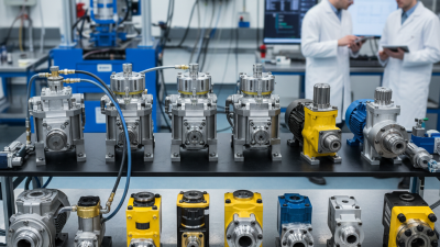
A gear pump is simple and durable. Vane and piston pumps can support different performance requirements. Engineers select them according to pressure, speed, temperature, duty cycle, and maintenance conditions. A relief valve helps limit excessive pressure. Clean fluid matters more than many beginners expect. Small particles can damage close-fitting components and shorten service life.
This article explains how a hydraulic pump motor works, from energy input to fluid delivery. It also examines common designs, operating principles, efficiency losses, and practical inspection points. Manufacturer data remains essential. A general explanation cannot replace the system’s service manual. Even experienced technicians can misdiagnose a noisy pump when the real problem is air, contamination, or restricted suction. Careful testing is safer than guessing.
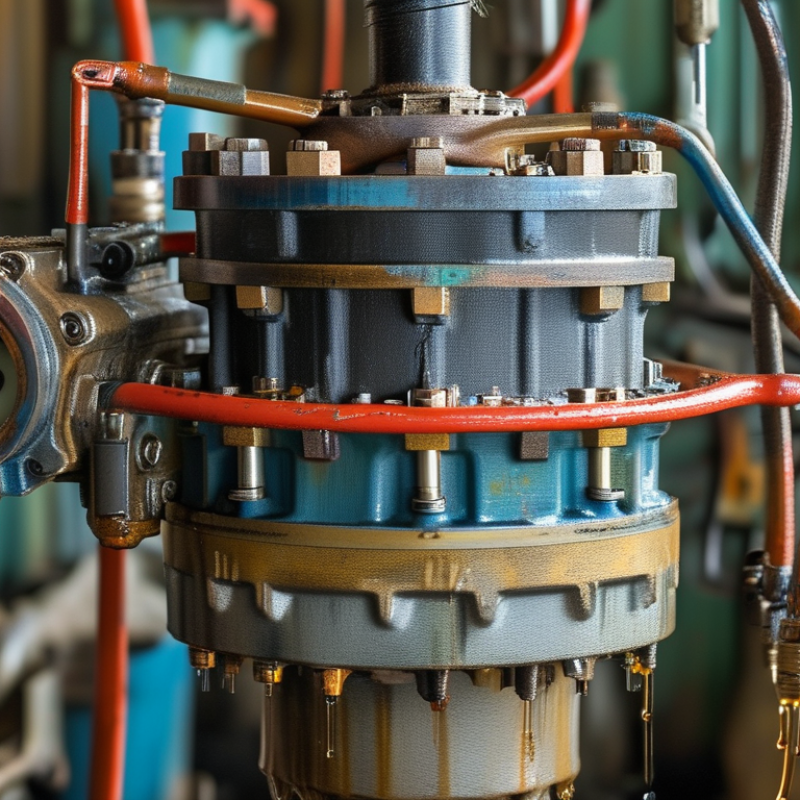
A hydraulic pump motor is the drive unit that powers a hydraulic pump. The motor converts electrical energy into rotating mechanical force. The pump then transforms that rotation into fluid flow and pressure. Together, they move pressurized oil through hoses, valves, and actuators.
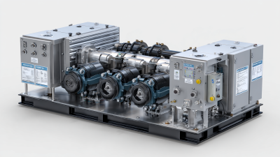
The main components include the electric motor, pump, coupling, reservoir, filter, pressure relief valve, and control valves. The motor shaft connects to the pump through a coupling. This connection must stay aligned. Even slight misalignment can create vibration, heat, and premature wear. The pump draws fluid from the reservoir and sends it into the hydraulic circuit. The relief valve protects the system when pressure rises beyond a safe setting. Filters capture particles that could damage close-fitting parts.
In practical maintenance work, unusual noise often provides the first warning. A whining sound may indicate low fluid, blocked suction, or air entering the system. A warm motor does not always mean failure, but continued overheating deserves attention. Diagnosis is not always perfect. A small assumption can lead to the wrong repair.
Tips: Check fluid level, filter condition, shaft alignment, and electrical connections regularly. Keep the reservoir clean and use the specified hydraulic fluid. Never inspect moving parts while the motor is energized. Temperature and pressure readings are more reliable than guesswork.
A hydraulic pump motor usually refers to the motor that drives a hydraulic pump. The motor receives electrical energy and creates mechanical rotation. This rotation turns the pump shaft through a coupling or direct connection. The pump then moves hydraulic fluid through the system.
The process starts inside the motor. Electrical current produces a magnetic field around the windings. That field interacts with the rotor and creates torque. Torque is the turning force that rotates the shaft. As the shaft spins, the pump draws fluid from a reservoir and pushes it toward valves, cylinders, or hydraulic motors. Pressure develops when the fluid meets resistance. Flow describes movement, while pressure reflects resistance. They are related, but not identical.
Real systems are less perfect than diagrams suggest. Heat, friction, leakage, and poor alignment reduce efficiency. A faint whine or rising motor temperature can signal trouble, although symptoms can overlap. Measuring current, fluid temperature, pressure, and vibration gives better evidence than guessing. Maintenance experience matters here. I have found that small installation errors can create large operating problems over time.
What Is a Hydraulic Pump Motor and How Does It Work?
A hydraulic pump motor converts mechanical energy into fluid power. The motor turns the pump shaft, while the pump creates a controlled flow of hydraulic oil. Pressure develops only when that flow meets resistance, such as a cylinder load or a valve restriction. Pressure is not created by the motor alone.
Inside a positive-displacement pump, rotating gears, pistons, or vanes capture oil at the inlet. The moving parts carry it toward the outlet, where the smaller volume raises pressure. A 2023 Fluid Power World industry survey places many industrial hydraulic systems between 100 and 350 bar. Actual pressure depends on load, pump displacement, and system settings. Small clearances matter. Internal leakage reduces output and increases heat.
The motor must supply enough torque for the required pressure and flow. A 30 L/min pump operating at 200 bar delivers about 10 kW of hydraulic power before losses. The calculation is simple: power equals pressure multiplied by flow, with unit conversion included. A 2024 National Fluid Power Association industry outlook also highlights efficiency as a major design concern across mobile and industrial equipment. In practice, total efficiency often falls below 85 percent. That gap becomes heat. Too much heat damages seals and thins the oil. A useful warning: a larger motor cannot repair poor sizing, restricted suction lines, or contaminated fluid. Real machines are less tidy. Testing flow, temperature, and pressure under load remains essential.
A hydraulic pump motor is the prime mover behind a hydraulic pump. It spins the pump shaft, creating flow from mechanical energy. Pressure appears only when that flow meets resistance.
Electric induction motors suit steady factory duty, while servo motors provide faster control and precise positioning. Diesel engines remain useful on mobile equipment where grid power is unavailable.
Pump selection changes system behavior. Gear pumps are compact, durable, and economical, but usually offer limited flow control. Vane pumps run quietly and handle moderate pressure.
Piston pumps support higher pressure and variable displacement, making them common in presses, excavators, and injection equipment. A fixed-displacement pump moves nearly the same volume per revolution.
A variable-displacement pump adjusts output, reducing throttling losses. The difference is tangible: one may keep pushing oil through a relief valve, while the other can slow production when demand falls.
The International Energy Agency reports that electric motor systems consume about 53% of global electricity. The U.S. Department of Energy’s Industrial Motor Systems Market Assessment also estimated motors used 23% of U.S. electricity consumption.
These figures make motor efficiency more than a maintenance detail. Correct sizing, alignment, filtration, and temperature control matter.
ISO 4413 also stresses safe hydraulic design and controlled energy release. A neat selection chart can mislead. Real machines face contaminated oil, cold starts, pressure spikes, and imperfect maintenance.
What Is a Hydraulic Pump Motor and How Does It Work?
A hydraulic pump motor combines an electric motor or engine with a hydraulic pump. The motor supplies rotation, while the pump converts that rotation into fluid flow. System pressure develops when the oil meets resistance from valves, cylinders, or other loads. Performance depends on delivering steady flow at the required pressure without excessive heat or noise.
Oil viscosity strongly affects efficiency. Cold oil creates drag, while overheated oil leaks internally and loses lubrication. Contamination is equally serious. Fine metal particles can damage gears, pistons, seals, and control valves. A blocked inlet filter may cause cavitation, producing a sharp rattling sound and damaging pump surfaces. Correct shaft alignment matters too. Even slight misalignment can increase vibration and bearing wear. Field inspections often find that poor hose routing creates unnecessary restriction. Small details matter.
Service life also depends on duty cycle, relief-valve settings, and maintenance intervals. Running continuously near maximum pressure shortens component life, even when the pump appears normal. Keep the reservoir clean, monitor oil temperature, and inspect connections for leaks. Measure flow and pressure, rather than trusting sound alone. That assumption can be misleading. A clean filter does not prove clean oil, and low noise does not guarantee efficiency. In practice, maintenance records are sometimes incomplete, making diagnosis slower and less certain. Regular testing gives technicians better evidence before replacing expensive parts.
| System Element or Factor | How It Works or What It Measures | Typical Values or Operating Range | Effect on Performance and Efficiency | Effect on Service Life |
|---|---|---|---|---|
| Electric Motor | Converts electrical energy into rotary mechanical power to drive a hydraulic pump. | Common industrial speed: 1,500–3,600 rpm | Correct motor sizing prevents overload, excessive heat, and inefficient operation. | Proper cooling, alignment, lubrication, and electrical protection reduce bearing and winding damage. |
| Hydraulic Pump | Converts mechanical shaft power into hydraulic flow and pressure. | Flow depends on displacement and speed; pressure is determined by system resistance and the relief setting. | Higher volumetric and mechanical efficiency produces more useful hydraulic power with less heat generation. | Clean fluid, adequate lubrication, correct inlet conditions, and protection from cavitation are essential. |
| Hydraulic Motor | Converts pressurized hydraulic fluid into rotary mechanical torque and speed. | Speed and torque vary with flow, pressure, and displacement. | Motor efficiency affects available output torque, speed stability, and total system energy consumption. | Contamination, shock loads, excessive pressure, and insufficient lubrication can accelerate wear. |
| Gear Pump or Gear Motor | Uses meshing gears to transfer hydraulic fluid between the inlet and outlet ports. | Typical pressure range: approximately 100–250 bar; application-dependent | Simple construction provides reliable operation, but internal leakage generally increases as components wear. | Usually tolerant of moderate operating conditions, but abrasive contamination can damage gears and bushings. |
| Vane Pump or Vane Motor | Uses sliding vanes in a rotating rotor to create changing volume chambers. | Typical pressure range: approximately 70–175 bar; application-dependent | Can provide relatively smooth flow and moderate noise levels when operated within its rated pressure range. | Vanes and cam surfaces are sensitive to contamination, poor lubrication, and excessive wear clearances. |
| Axial Piston Pump or Motor | Uses pistons arranged parallel to the drive shaft to handle high pressure and variable displacement. | Typical pressure range: approximately 210–350 bar; some designs operate higher | Generally offers high efficiency and precise control, especially in variable-displacement systems. | Requires clean fluid, correct case-drain conditions, proper filtration, and careful pressure control. |
| Flow Rate | The volume of hydraulic fluid delivered or consumed per unit of time. | Usually expressed in L/min or gal/min | For a fixed displacement, increasing flow increases actuator or motor speed but also increases power demand. | Excessive flow can cause high line velocity, pressure losses, turbulence, and heat. |
| Pressure | The force exerted by hydraulic fluid per unit area; it determines available actuator force or motor torque. | Usually expressed in bar, MPa, or psi | Higher pressure increases output force or torque, but also increases leakage, stress, and heat if efficiency is poor. | Operating above the rated pressure can deform components, damage seals, and shorten fatigue life. |
| Displacement | The fluid volume moved per shaft revolution, normally stated in cm³/rev or in³/rev. | Fixed or variable displacement | Larger displacement produces more flow at the same speed or more torque at the same pressure. | Variable-displacement units may reduce energy losses, but their control mechanisms require clean fluid and correct adjustment. |
| Volumetric Efficiency | The ratio of actual delivered or consumed flow to theoretical flow based on displacement and speed. | Often approximately 85–98% in healthy units, depending on type and operating conditions | Low volumetric efficiency indicates internal leakage and reduces speed, flow capacity, or system responsiveness. | It normally declines as clearances, seals, gears, vanes, or pistons wear. |
| Mechanical Efficiency | The proportion of input mechanical power converted without losses from friction and mechanical resistance. | Often approximately 90–98% in well-maintained units | Low mechanical efficiency increases required drive power and produces additional heat. | Viscosity that is too high, poor lubrication, misalignment, and bearing wear reduce efficiency and durability. |
| Overall Efficiency | Combines volumetric and mechanical efficiency to show how effectively input power becomes useful hydraulic or mechanical output. | Common practical range: approximately 70–95%, depending on unit type and load | Higher efficiency lowers operating costs and reduces the size of the cooling system required. | Persistent low efficiency usually indicates wear, contamination, incorrect viscosity, or operation outside the rated range. |
| Hydraulic Fluid Viscosity | Describes the fluid’s resistance to flow and its ability to maintain lubricating films. | Typical hydraulic-fluid operating range: approximately 15–40 cSt; manufacturer limits apply | Fluid that is too thick causes startup losses and inlet restriction; fluid that is too thin increases leakage and wear. | Maintaining the recommended viscosity range protects bearings, gears, pistons, vanes, and seals. |
| Fluid Temperature | Measures the operating temperature of the hydraulic fluid and surrounding components. | Common target range: approximately 40–60°C; limits vary by fluid and equipment | Excessive temperature lowers viscosity, accelerates oxidation, and increases leakage and energy loss. | Repeated overheating hardens seals, degrades fluid additives, and reduces component fatigue life. |
| Contamination Level | Indicates the concentration of particles, water, air, or chemical degradation products in the fluid. | Cleanliness is commonly specified using an ISO 4406 code | Particles can obstruct valves, increase leakage, reduce efficiency, and cause erratic operation. | Contamination is one of the main causes of premature failure in hydraulic pumps and motors. |
| Cavitation and Aeration | Cavitation occurs when inlet pressure is too low; aeration occurs when air enters the hydraulic circuit. | No intentional cavitation or aeration is acceptable during normal operation | Both conditions cause noise, vibration, unstable output, pressure fluctuations, and reduced efficiency. | Imploding vapor bubbles and air impacts can pit metal surfaces and damage bearings, seals, and rotating groups. |
| Filtration | Removes harmful particles from the hydraulic fluid before they reach sensitive components. | Filter rating depends on component sensitivity and the required ISO cleanliness code | Correct filtration maintains valve response, reduces internal leakage, and supports stable efficiency. | Filters must be correctly sized, monitored for restriction, and replaced at suitable intervals. |
| Operating Speed | The rotational speed of the pump or motor shaft. | Must remain within the unit’s minimum and maximum rated speed | Excessive speed can increase flow and friction losses; insufficient speed may reduce lubrication and control stability. | Repeated overspeeding increases bearing, seal, and rotating-group stress. |
| Maintenance Practices | Includes fluid analysis, filter replacement, leak inspection, temperature monitoring, and alignment checks. | Inspection intervals should follow operating conditions and equipment requirements | Condition-based maintenance helps preserve efficiency and identify performance degradation early. | Regular maintenance can significantly extend service life by preventing contamination, overheating, and lubrication failures. |
How can we help you?
Call to 0034 943884600 Contact usWe use cookies to ensure that we give you the best experience on our website. If you continue without changing your settings, we'll assume that you agree to receive cookies on the HINE website. For more information read our cookie policy page, click the link for more information.plugin cookies
ACEPTAR